
Newsletter Sign Up
Subscribe to get the latest news and updates. No spam , we promise.

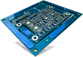
The printed circuit board (PCBs) is an integral element of electronic devices in use today. These PCBs are manufactured using several small and fine components, which are carefully designed and mounted on the board to get the desired outcome. Thus, circuit board manufacturing is a complex and lengthy process, demanding meticulous attention to details. There are two parts to the PCB manufacturing process – PCB fabrication services, during which circuit board layout is constructed and assembly, wherein all the components are mounted on the circuit board. Both methods are important, and any minor error may impact on the performance. This post discusses the PCB fabrication in detail, and also focuses on important guidelines to ease the process.
This section emphasizes the PCB fabrication process in detail. An understanding of the steps involved in PCB manufacturing can provide enlightenment and strategies that make the fabrication process easier. So, let’s have a look at it.
The PCB fabrication process is divided into three distinct stages – fabrication, component procurement, and assembly. Though these stages are different from each other, they are interrelated, and many design choices impact all of these. For instance, each component mounted during circuit board assembly and the footprint for the pads fixed on the PCB during the fabrication process should exactly match the component package type acquired.
To ease the PCB fabrication process, it is important to understand the circuit board steps along with their manufacturability issues that may arise and threaten the board’s performance.
In this, the image for inner and outer layers are created on the circuit board. If not properly aligned, then it can cause problems for drilling vias and mounting holes.
This is one important step in the fabrication process as it removes the unwanted copper area. Only the desired copper area remains on traces and pads. An improper etching process may result in traces-related issues. Traces without adequate spacing will prevent signal flow which results in halts in the fabrication until corrected.
The alignment of circuit board stackup is performed during fabrication. During this step, the PCB layers are pressed and aligned. Alignment issue may lead to operational failure.
Drilling can be plated through holes or PTHs, non-plated through holes, or vias. Just like the alignment issues, the spacing and clearance issues impact solder masking. Aspect ratio is also important here as it defines what drilling types can be used.
Etching removes the excess copper from a panel and exposes traces and pads.
Here, the conductive material for PTHs and vias is performed. Outgassing is a major issue that may occur during assembly.
Solder mask acts as a covering guard. It covers the whole surface expect over pads and traces that protect the circuit boards. This guard prevents several assembly problems such as solder bridging that can lead to shorts and damages.
This is one of the vital steps in the fabrication process as it prints the important information on the circuit boards. Silkscreen errors can hamper the assembly process and may negatively affect the operation.
As discussed before, errors in the circuit board design can lead to dangerous issues, and if not detected before fabrication, then these major issues demand expensive repair. In fact, one will have to have a new board fabricated in addition to doing a redesign. Fortunately, these errors can be avoided by employing strategies, which are built upon design for manufacturability (DFM). With the following guidelines, you can make the fabrication process efficient.
This is the first and most effective rule of DFM usage, which will be applicable for the equipment used by the manufacturer to construct the board. In many cases, some default rules may be applied by the manufacturer. However, it is recommended not to rely upon these because CMs will furnish you with rules and tolerances. Rather, you can download rule files which can be directly uploaded into the PCB design package.
Before submitting files for fabrication, one should correct DRC violations as the design changes will correct some errors.
After you submit your design files to CM, they will again perform a DRC check. If there are any errors, then make appropriate correction to avoid excess expenses.
To create a superior and performance-driven circuit board design, it is imperative to consider the above guidelines. If you’re interested to know about PCB fabrication services, you can contact industry-leading manufacturers like Creative Hi-Tech. Their highly experienced and skilled experts will assist you.
• Develop the Engineer Inside your Kids by Gifting them PCB Fabrication Kits